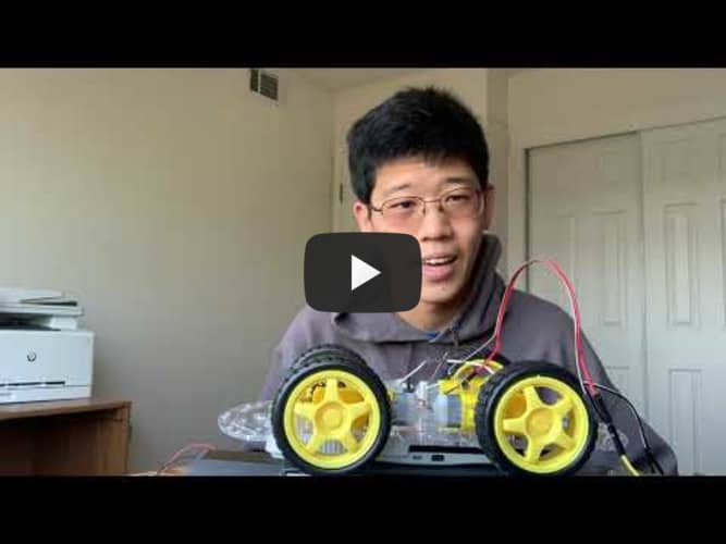
# Ball Tracking Robot
This project intrigued me because it combines computer vision with robotics. In piecing together this robot car, I learned a lot about both the coding aspects of the software and mechanical techniques such as soldering the hardware. Most importantly however, I learned how to analyze and overcome unexpected setbacks.
| Engineer | School | Area of Interest | Grade |
|---|---|---|---|
| Oliver | Leland High School | Electrical Engineering | Incoming Senior |

Final Milestone
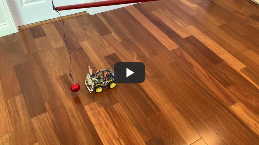
My final milestone was getting the robot to be able to track an object! The computer vision code is actually based off of sensing color, which means that I was able to modify the code to target red objects. One of the major hurdles in this stage was separating the robot from its wired connections to a monitor and a wall socket for power. To run the code without a monitor, I devised a method to start the program everytime a new terminal was opened. That way, I could use a wireless keyboard to start and stop the process.

For power, I used a power bank with some extension cords wrapped around the front of the chassis. Besides serving as a pseudo-bumper, I could now charge the power bank when not in use, and then disconnect the extension cords to allow the car to roam freely.

There’s also another battery pack in the back that is used to power the motors, whereas the powerbank powers the Raspberry Pi.


Here are some pictures of the development process:
Prototype breadboard without internal battery (power bank):

Opening up the chassis:

Adding the battery and extension cords:


Test Drive:

Circuit Diagram

Code

Second Milestone
My second milestone was using the camera to control the motors of the car. This is a crucial aspect of the self-driving car, since it needs to be able to track and recognize where the desired object is, and then respond accordingly through driving towards that object. At first, I encountered a problem in that the motors were wired incorrectly, leading to a forwards command becoming a right turn, for example. To solve this, I manually gave the robot some commands to test which connections corresponded with which wheels, and was able to fix the problem. The next step is to incorporate the ultrasonic sensors and integrate the electronics onto the chassis in such a way that the car can run on its own (separate from a monitor/wired power source).
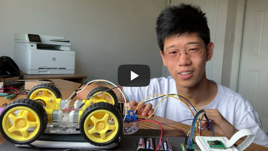
First Milestone
My first milestone was assembling the chassis of the robotic car and attaching motors. Each of the four motors has two electrodes for connections, so I had to figure out the best way to wire them together. Since I’m using “tank steering”, where rotating the wheels on one side faster makes the car turn, I chose to connect the two motors on each side of the car together first. One of the challenges that I faced was that the bottom screws on each motor were actually positioned too close to the acrylic chassis, making it impossible to rotate a nut to fasten them. To solve this, I reversed the direction of these bottom screws so that the nut would be positioned on the outside of the chassis. I’ve been able to use a battery to drive each of these motors individually, so the next step is to use a motor driver and the Raspberry Pi to control the motors using code.